4. Transmission Errors
Data Communication & Networking
3rd Semester
Data Link Layer
- Responsible for taking the data and transforming it into a frame with header control and address information
- Physical path communication
- Error detection
- Error correction
- Resolve competing requests
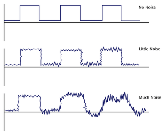
Noise and Errors
Noise is always there. If there’s too much noise in a communication line, signal will be lost or corrupted.
White noise
- Also known as thermal or Gaussian noise
- Relatively constant and can be reduced
- Strong white noise can completely disrupt the signal
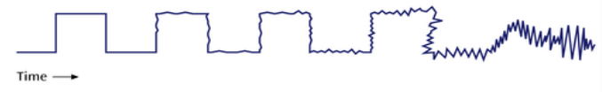
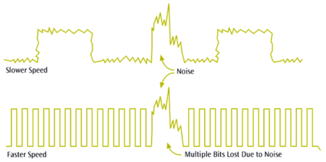
Impulse Noise
- One of the most disruptive forms of noise
- Random spikes of power
- Difficult to remove from an analog signal
- Can damage more bits if the bit rate is higher
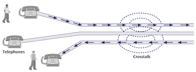
Crosstalk
- Unwanted coupling between two different signal paths
- Relatively constant and can be reduced with proper measures
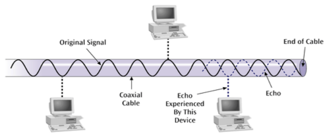
Echo
- Reflective feedback of a transmitted signal as the signal moves through a medium
- More often occurs in coaxial cable
- If the echo is bad enough it could interfere with original signal
- Relatively constant and can be significantly reduced
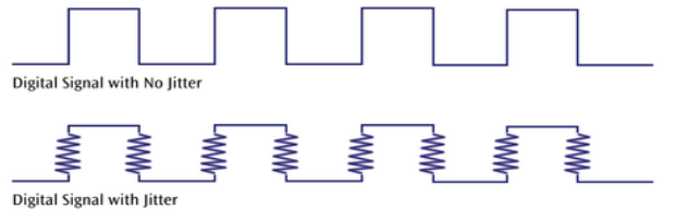
Jitter
- Caused by small timing irregularities during the transmission of digital signals
- Occurs when a digital signal is repeated over and over
- Jitter causes systems to slow down their transmission
- We can reduce jitter through shielding
Delay distrortion
- Occurs because of the velocity of a propergating signal over a medium varies with the frequency of the signal
- Can be reduced using equalizers
Attenuation
- The continuous loss of a signal’s strength as it travels through a medium
- To mitigate
- Use less lossy medium
- Use amplifiers
Distortion
- As signals travel it get distorted
- Change shape
- Successive bits may merge
Interference
- Unwanted signal from outside sources
- Difficult to diagnose
Error Prevention
- Proper shielding of cables
- Replacing older media with new equipment
- Proper use of repeaters and amplifiers
- Observing stated capacities of the media
Information Redundancy
Coding
- A data word with d bits is encoded into a code-word with c bits c > d
- To extract original data - c bits must be decoded
- If the c bits do not constitute a valid code-word, an error is detected
- For certain encoding schemes - some types of errors can also be corrected
Separability of a Code
- A separable code has separate fields for the data and code bits
- When decoding we can disregard code bits
- Code bits can be processed separately to verify the correctness of the data
- A non-separable code has the data and code bits integrated together
Parity Codes
- Simplest of the codes
- Parity code includes d data bits and an extra bit to hold the parity
- Even parity :
- Total number of 1’s of the d+1 length word (including parity bit) is even
- Odd parity:
- Total number of 1’s of the d+1 length word (including parity bit) is odd
2 Dimensional Parity
- Uses both Longitudinal Redundancy Check (LRC) and Vertical Redundancy Check (VRC)
- Identifies a unique erroneous bit
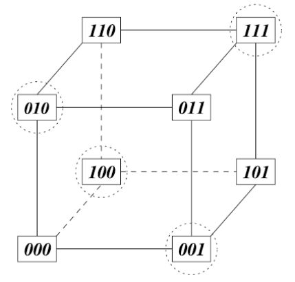
Hamming Distance
- Hamming distance between two code-words shows the number of positions in which the two words differ
- Two words are connected by an edge if their hamming distenace is 1
Hamming Code
- Based on Hamming distance
- Assigns multiple parity bits to cover each bit of data
- Many different hamming code schemes exist
- Ex: (7,4) Single Error Correcting Hamming Code
(7,4) Single Error Correcting (SEC) Hamming Code
- Can correct 1-bit errors
- Calculating parity bits
where r = number of parity btis, m = message bits
- Ex: f m=4, r = 3
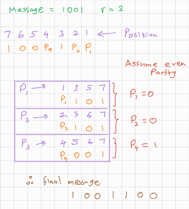
Parity Bits placement
- In the resulting codeword, parity bits can be placed at different places. Placement affects how easy/difficult to detect and correct errors
- One way is to place parity bits at paces corresponding to powers of 2
Parity bit coverage
(7,4) Hamming code uses 3 parity bits (
- P₁ (position 1): Covers positions 1, 3, 5, 7 → P₁
- Covers positions with bit 0 = 1₂
- P₁ = XOR of bits at positions 1,3,5,7
- P₂ (position 2): Covers positions 2, 3, 6, 7 → P₂
- Covers positions with bit 1 = 1₂
- XOR of bits at positions 2,3,6,7
- P₄ (position 4): Covers positions 4, 5, 6, 7 → P₄
- Covers positions with bit 2 = 1₂
- XOR of bits at positions 4,5,6,7
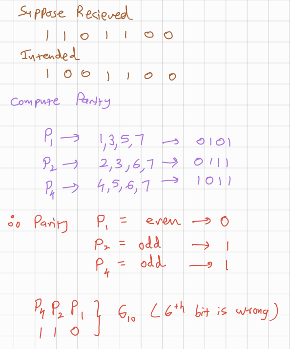
For example let’s take a message m =
1001
Error Detection
When receiving the code-word use parity bits to check the parity of each parity bit
- P₁ check: positions 1,3,5,7 → result 0101 = 0 (even parity ✓)
- P₂ check: positions 2,3,6,7 → result 0111 = 1 (odd parity ✗)
- P₄ check: positions 4,5,6,7 → result 1011 = 1 (odd parity ✗) The syndrome is formed by combining the parity bits ex: 110₂ = 6₁₀ (6th bit is the wrong bit) This syndrome value shows the place of the error bit
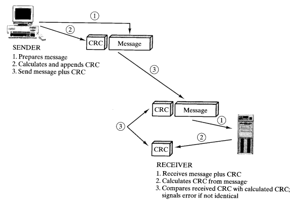
Cyclic Redundancy Checksum (CRC)
- A non separable code
- Treats the packet of data to be transmitted as a large polynomial.
- Takes the message polynomial and using polynomial arithmetic, divide it by a given generating polynomial
- Quotient is discarded, but the remainder is attached to the end of the message (remainder (mod) arithmetic)
- Message (with the remainder) is transmitted to the reciever
- The reciever divides the message and remaider by the same generating polynomial
- If remainder not equal to zero, there was an error during transmission
CRC Example
- Message = 101101
- CRC Polynomial = x³ + x² + 1 = 1101 (in binary)
- Number of CRC bits = 3
Step 1: Append zeroes to your message
Add 3 zeros (number of CRC bits) to the end of your message
- Original message: 101101
- Message with zeros: 101101000
Step 2: Perform modulo-2 long division
Divide the extended message (101101000) by the polynomial (1101) using XOR operations instead of regular subtraction:
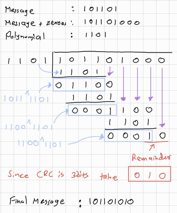
Therefore complete code-word : 101101010